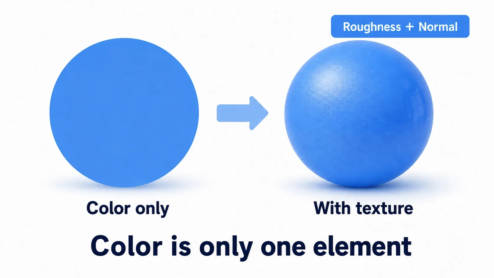
You've applied a texture to a 3D model and it displays fine. But it still looks cheap. Like a plastic toy, nothing like the surfaces in the examples you've seen. Nearly everyone who starts working with materials passes through this.
The cause is usually that every pin except Base Color is empty. A UE material isn't a "paint the surface" feature, it's a system for defining how light bounces off this surface, so color is only one ingredient. This article organizes the four pins you need first, then goes all the way to parameterizing a material and mass-producing color variants with Material Instances.
What You'll Learn
- A material decides how light bounces, not just color
- Roughness decides surface character (leave it empty and things look cheap)
- Metallic is 0 or 1, values in between are almost never used
- Five nodes are enough to get started
- Hands-on: parameterize a material and build color variants with Material Instances
A Material Is "How Light Bounces"
UE materials are built around PBR (physically based rendering). It sounds intimidating, but the meaning is simple: imitate how real-world materials bounce light. That's all.
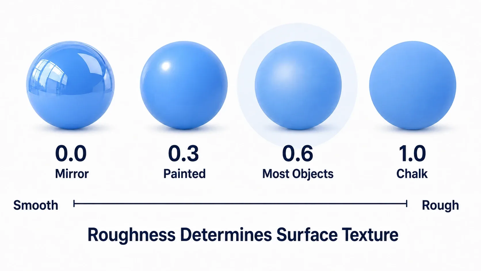
Why can you tell iron, wood, and cloth apart in the real world? Not by color alone. It's because they bounce light differently. Iron reflects sharply enough to show a reflection; cloth scatters light into a blur. Expressing that difference numerically is the material's job.
So putting brown in Base Color won't make something look like wood. You haven't told it how wood bounces light.
There's another payoff: a properly built PBR material holds up under any lighting. Outdoors at noon, indoors at night, the same settings look natural. Not having to retune per lighting setup is PBR's biggest advantage.
The Four Pins to Learn First
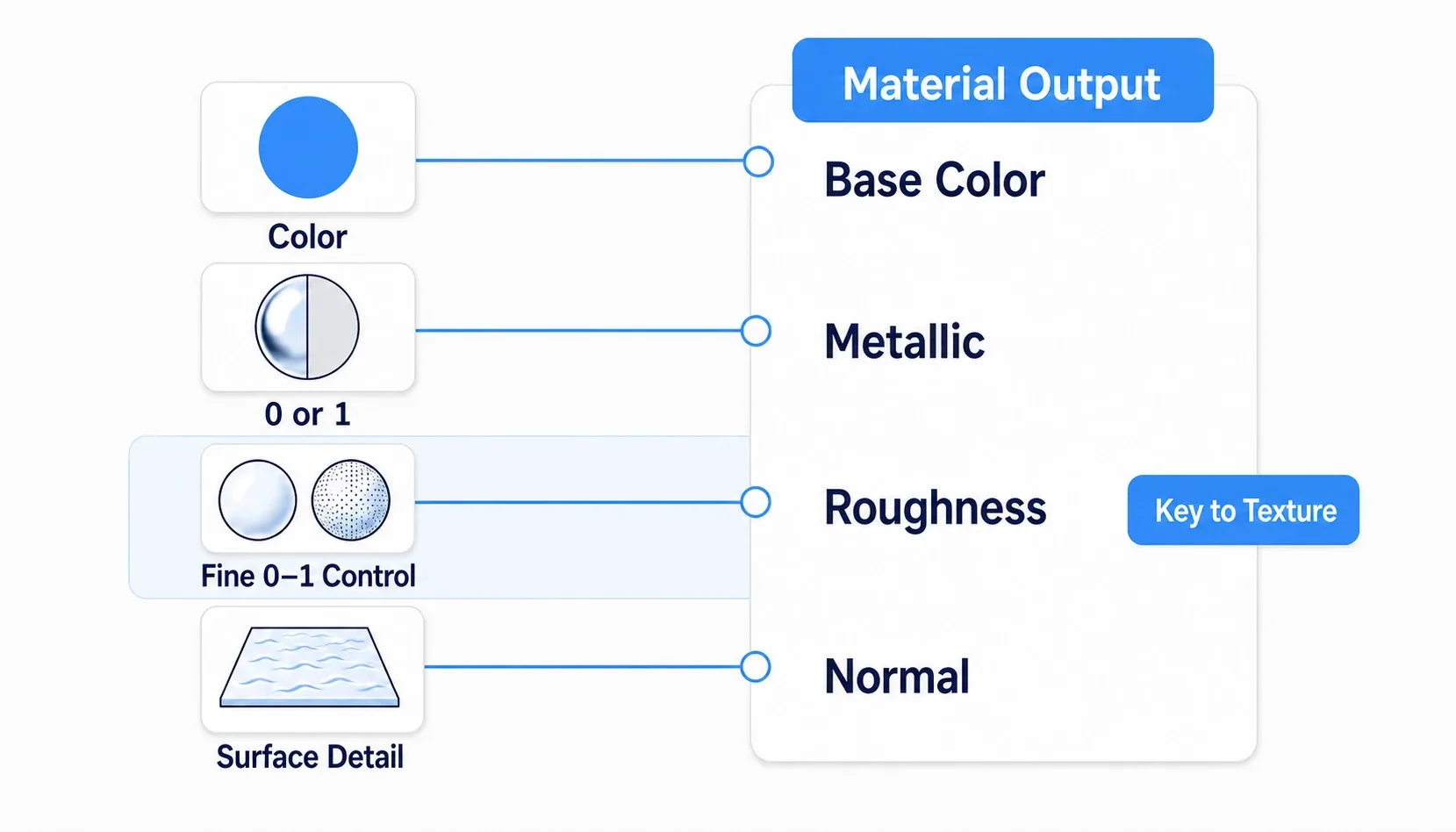
The material output node has plenty of pins, but four are what you learn first.
| Pin | What It Decides | What Goes In |
|---|---|---|
| Base Color | The raw color | Color (RGB) |
| Metallic | Is it metal? | 0 or 1 (values in between are almost never used) |
| Roughness | Surface roughness | The full 0–1 range |
| Normal | Apparent surface detail | A Normal Map texture |
Metallic is 0 or 1. There's almost no such thing as a "50% metallic" substance in reality. Wood, stone, plastic, cloth, and skin are all 0; iron, gold, and copper are 1. For mixed cases like rusted iron, paint the split with a mask texture: "1 here, 0 there."
Roughness is the star of surface character. Adjusting it is most of what material work actually is.
| Value | Appearance | Examples |
|---|---|---|
| 0.0 | Mirror-sharp reflection | A polished mirror, still water |
| 0.2–0.4 | Glossy | Painted cars, a wet floor |
| 0.5–0.7 | Settled, ordinary surfaces | Most things live here |
| 1.0 | Fully matte | Chalk, coarse fabric |
Materials that feel "cheap" usually have Roughness left unset (at its default) or pushed to an extreme. Try putting something around 0.5 in there first. That alone changes the impression.
Normal is the pin that shows detail without changing geometry. Brick mortar lines, screw threads, all without adding polygons. You just connect a Normal Map texture, so there's not much to get wrong.
Connected a Normal Map and the detail looks inverted? UE expects the DirectX convention. Blender and others sometimes export in the OpenGL convention, where the green channel is flipped. Open the texture asset and check
Flip Green Channelto fix it.
Five Nodes Are Enough
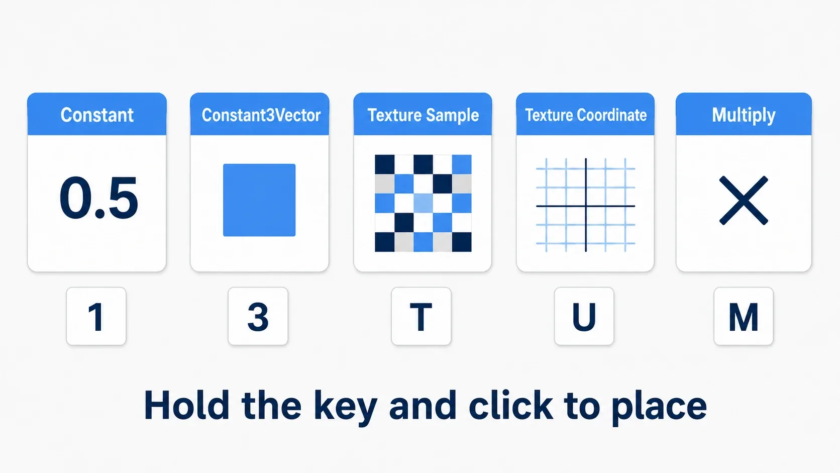
The material editor has hundreds of nodes, but five kinds will do at the start.
| Node | What It Does | Shortcut |
|---|---|---|
| Constant | A single number (Roughness, etc.) | 1 + click |
| Constant3Vector | A color (RGB) | 3 + click |
| Texture Sample | Reads a texture | T + click |
| Texture Coordinate | Adjusts tiling (repetition) | U + click |
| Multiply | Multiplication (brightness, masking) | M + click |
Holding a key and clicking the graph places the node instantly, and learning these genuinely changes how fast you work.
A word on where Multiply comes in. Multiply a texture by 0.5 and it darkens; by 2.0 and it brightens. That's the basic use. Going further, multiplying a color by a mask lets you express things like "only this part is rusted."
One more you'll definitely reach for eventually is Lerp (Linear Interpolate). It blends A and B by the ratio in Alpha.
Alpha = 0→ A comes through unchangedAlpha = 1→ B comes through unchanged- Plug a mask texture into Alpha and only the white areas become B
Blending dry ground with wet ground using a puddle mask? That's Lerp.
Hands-On: A Metal Material With Changeable Color
Equipment color variants in an RPG, car paint in a racing game, weapon skins in an FPS. "Same material, different color" shows up in huge quantities in every genre. Doing it by duplicating materials falls apart, so let's learn the right way.
Setup: no textures needed. We'll start with a solid-color metal and make its color changeable afterward.
| Type | Name | Contents |
|---|---|---|
| Material | M_Metal_Base | The parent material we're about to build |
| Material Instance | MI_Metal_Gold / MI_Metal_Steel | Color variants (created later) |
| For checking | Three Spheres | Lined up in the level |
Step 1: Create the material. Right-click in the Content Browser → Material. Name it M_Metal_Base and open it.
Step 2: Build the surface with fixed values first. Place and connect the following in the graph.
3+ click to place aConstant3Vector, double-click to pick a color (gold for now: R=1.0 / G=0.77 / B=0.34) → into Base Color1+ click to place aConstant, set it to 1.0 → into Metallic- Place another
Constant, set it to 0.25 → into Roughness
Hit Apply and look at the preview sphere. You should have a gold sphere reflecting the environment like a mirror.
Now move only Roughness to get a feel for it. At 0.05 it's mirror-like; at 0.6 it's a dull metal. You can see with your own eyes that Roughness is what decides surface character.
Step 3: Parameterize it. Here's the real point of the exercise.
Right-click the Constant3Vector (the color) node → Convert to Parameter, and name it BaseColor. Do the same for the Roughness Constant and name it Roughness.
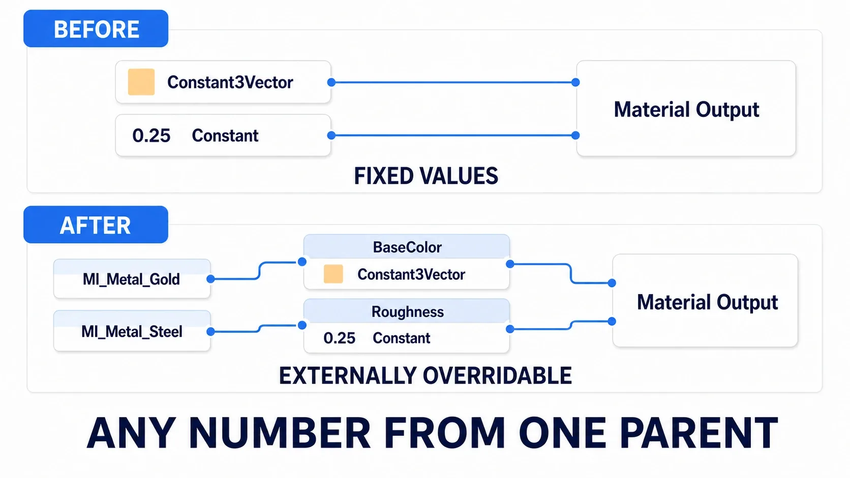
The nodes change appearance and now carry names. That means their values can be swapped from outside. Hit Apply and Save.
Step 4: Create a Material Instance. Right-click M_Metal_Base in the Content Browser → Create Material Instance. Name it MI_Metal_Gold and open it.
The Details panel lists BaseColor and Roughness. Tick the checkbox on the left to make one editable, then change the value. The preview updates instantly.
Follow the same steps for MI_Metal_Steel, setting BaseColor to gray (R=0.56 / G=0.57 / B=0.58) and Roughness to 0.35.
Step 5: Line them up and compare. Assign M_Metal_Base, MI_Metal_Gold, and MI_Metal_Steel to the three Spheres in your level.
All three should keep the same "metal" character while differing only in color and gloss. If you see that, it worked.
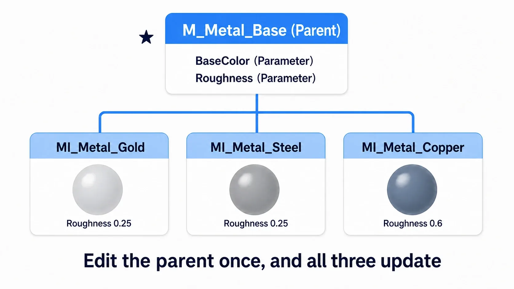
The real benefit of Instances starts here. Open M_Metal_Base and add a subtle scratch texture into Roughness. The moment you save, both the gold and the steel pick it up. Had you duplicated materials instead, you'd be repeating that edit on every copy.
If something's off, here's how to narrow it down.
- Looks pure black → Metallic is 1 but Base Color is too dark. Metal is visible through reflections, so with no light around it turns black
- Looks like plastic → Metallic is still 0
- Changing a value in the Instance does nothing → You haven't ticked the checkbox on the left of
Details - The parameters don't appear → You forgot
Convert to Parameterin the parent material, or didn't save
Two things to take away.
- Don't duplicate materials, create Instances: Visual differences go in Instances, structural changes go in the parent. Keep that split and you can fix everything at once later
- Instances are cheap: Duplicating a material compiles a new shader per copy, while an Instance only swaps parameters, so nothing compiles. The gap widens as the count grows
When you move on to textured materials, running Convert to Parameter on a Texture Sample lets Instances swap the texture too. Drive those parameterized values at runtime and you get effects like a flash of red the moment a character takes a hit (→ Changing Colors at Runtime with Dynamic Material Instances). If you want to adjust the color of the whole screen instead, Post Process Volume is a different angle on the problem.
Bonus: Good to Know for Later
Don't put pure black or pure white in Base Color. Real materials never absorb or reflect light completely. Keeping values roughly in the 30–240 range in RGB terms looks natural. Pure black leaves you with a black blob under any lighting.
Emissive isn't only "looks like it's glowing." With Lumen in UE5, an emissive surface actually lights its surroundings. That said, it needs enough area and enough intensity to matter, and small, weak emissives contribute almost nothing. To light a scene with a neon sign, you need Emissive values in the tens or higher.
Adjust tiling with Texture Coordinate. When a texture looks stretched, press U + click to place a Texture Coordinate, raise UTiling / VTiling, and connect it to Texture Sample's UVs. Parameterizing this too is handy, since you can then tune it per Instance.
There's also a newer material framework called Substrate. UE5 offers Substrate, which lets you layer multiple material behaviors together (the clear coat on car paint, oiled leather, blood and sweat on skin). Conventional materials are still what you get by default, so the four ideas you learned here — Base Color, Metallic, Roughness, Normal — remain the foundation. Enabling it changes how materials are authored, so get comfortable with the conventional form first.
Don't judge from the preview sphere alone. The material editor preview uses its own lighting environment. It isn't finished until you've placed it in the actual level and viewed it under your game's lighting. Dark scenes in particular change the impression dramatically.
Summary
When a material isn't working, check in this order.
| Symptom | Pin to Check |
|---|---|
| Cheap-looking, flat | Roughness (if unset, try around 0.5) |
| Looks like plastic | Metallic (set to 1 for metals) |
| Flat with no surface detail | Normal (connect a Normal Map) |
| Detail looks inverted | The texture's Flip Green Channel |
| Pure black | Base Color too dark / no light around it |
And one workflow rule: build color variants as Instances. The moment you duplicate a material, the number of places you'll have to fix later grows by one.
The material you're using right now, is its Roughness pin connected?