You made a hill with Landscape and hand-scattered trees with the Foliage tool. But when you try to fill a wide map, placing thousands of trees one by one isn't realistic. And even if you think "there were too many trees after all", the work of deleting and re-scattering is another chore.
Solving this "mass placement" by rules instead of by hand is PCG (Procedural Content Generation) . Write "where, what, and under what condition to scatter" into a graph, and placement is generated automatically, re-scattering instantly when you change the conditions. This article covers, from PCG's basics to growing a forest on a hill and removing trees only along a path, while actually growing a graph.
PCG appeared in UE5.2 as an Experimental feature and became Production-Ready in the UE5.7 generation. Either way you need to enable the plugin. Node names can change between versions, so check against the UE you're using.

What You'll Learn
- What PCG is: write "where, what, by condition" into a graph for auto-placement
- The division with the Foliage tool (scatter by hand / by rule)
- Growing trees with PCG Volume and Surface Sampler / Static Mesh Spawner
- Excluding cliffs with a slope filter
- Removing trees only along a spline (Difference)
- Hands-on: a graph with a forest on a hill and no trees on the path
What PCG Is
PCG (Procedural Content Generation) is a mechanism that decides placement by rules (a graph) . Rather than placing one by one by hand, connect "where, what, and under what condition" with nodes, and placement is auto-generated exactly as written.
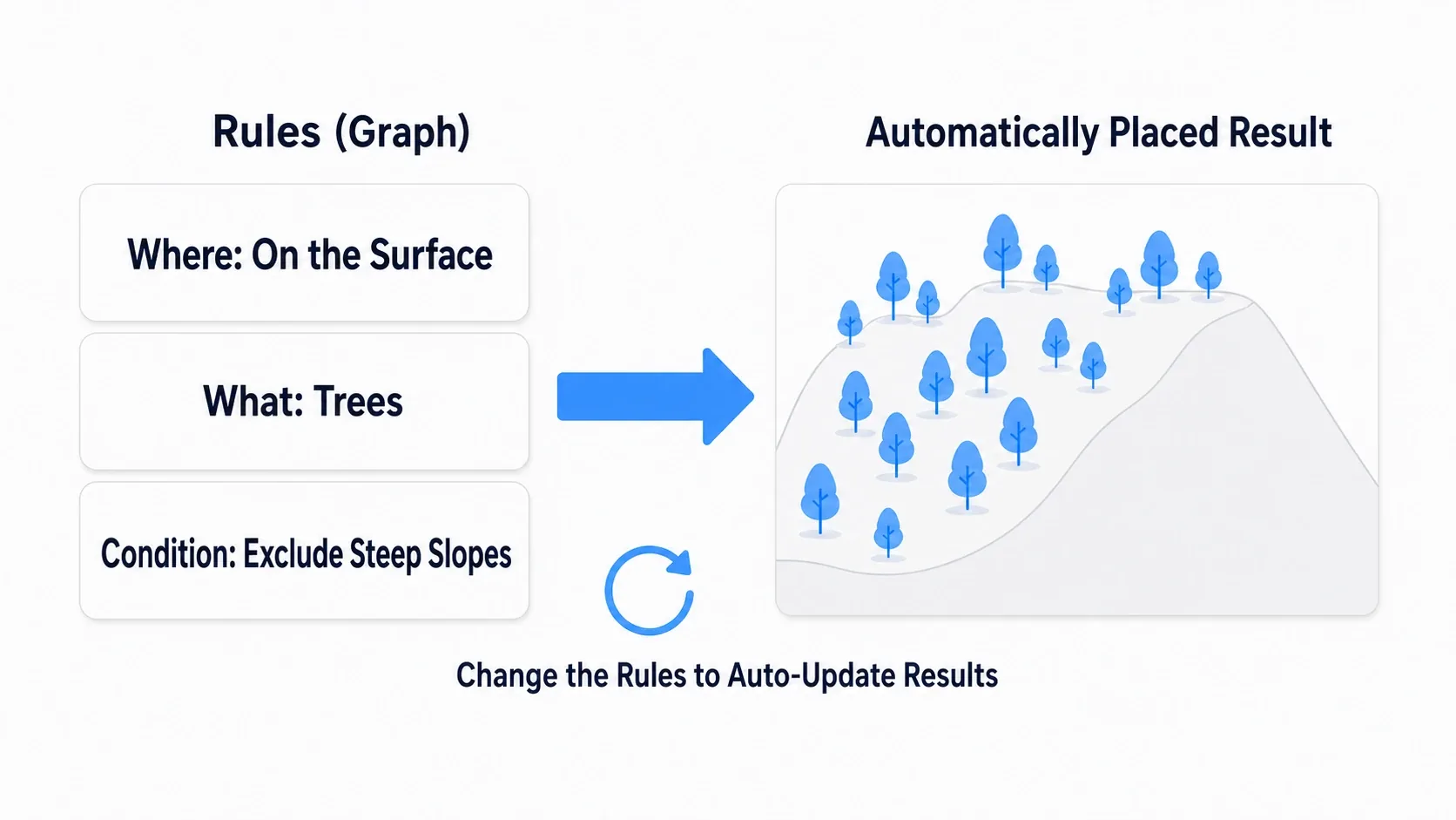
What's good about PCG? That redoing is free .
- Want to change the density → just change a number in the graph and everything re-scatters
- Don't want to grow on cliffs → just add one condition node
- Changed the shape of the path → the placement follows automatically
Hand-scattered Foliage and Actors needed re-placement with every change. Because PCG holds "rules" rather than "results", change the rules and the results auto-update . This is the key to making a wide map work solo.
The Division with the Foliage Tool
UE has long had the Foliage tool as a means to scatter trees and grass. Since its role differs from PCG, get the division down.
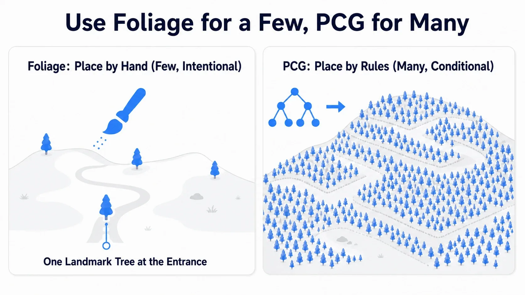
- Foliage tool (scatter by hand): place a small amount at aimed spots with a brush. It suits intended placement like "one marker tree beside the entrance" or "a few rocks at a highlight"
- PCG (scatter by rule): scatter a large amount over a wide area by graph conditions. It suits condition-driven mass placement like "forest over a hill" or "reeds packed along a riverbank"
The rule of thumb is Foliage for a small, intended placement, PCG for a large, condition-driven placement . Combining both, scattering the broad strokes with PCG and touching up only the highlights with Foliage, is also common.
Your First PCG: Growing Trees
First, let's auto-grow trees on a hill. PCG's minimal setup is a PCG Volume and a PCG graph inside it.
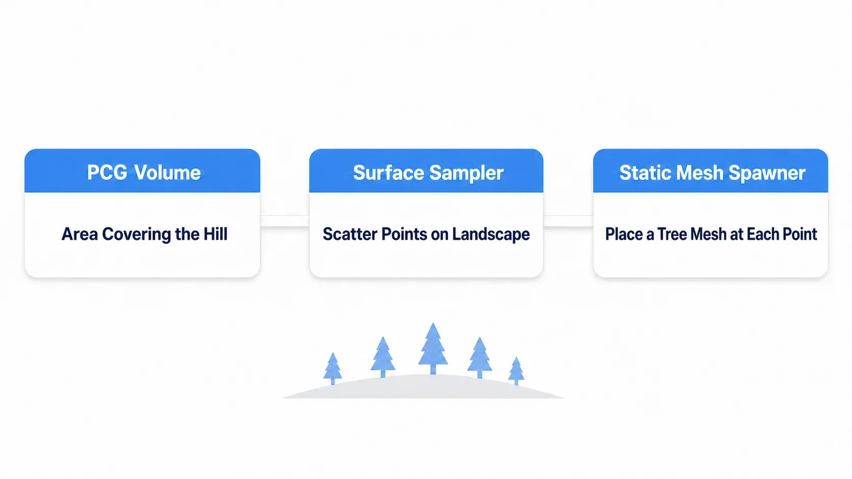
The steps go like this.
- Place a PCG Volume: place a PCG Volume in the level, covering the range you want trees (the hill)
- Make a PCG graph: make a PCG graph assigned to the Volume, and connect nodes inside it
- Surface Sampler: the node that "scatters points on a surface". Scatter points targeting the terrain (Landscape)
- Static Mesh Spawner: place tree Static Meshes at each scattered point
PCG graph (minimal setup)
Surface Sampler (scatter points on the Landscape surface)
  → Static Mesh Spawner (place tree meshes at each point)
Surface Sampler decides "where to scatter (points)", and Static Mesh Spawner decides "what to place (meshes)". These two line trees up on the hill. When no trees come out, first suspect whether the Surface Sampler's target points to the Landscape .
Excluding Cliffs with a Slope Filter
Scatter over the whole hill and trees grow even on sheer cliffs, which looks unnatural. So, narrow down where to scatter by condition .
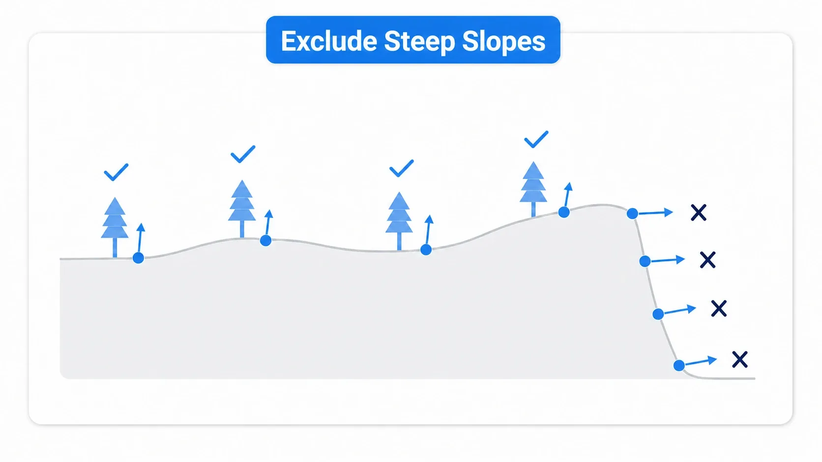
Each point scattered by the Surface Sampler holds information about the slope (normal) of its location. Using this, add one filter that discards points on steep slopes .
- Look at each point's slope and exclude points steeper than a threshold (cliff-like)
- Place trees with Static Mesh Spawner only on the remaining flat points
Now trees don't grow on cliffs, and a forest forms only on gentle slopes and flat ground. Placement gets smarter just by adding one condition node , that's PCG's strength. Scatterings like grass only on steep slopes and trees on flat ground can also be made with combinations of filters.
Removing Trees Only on the Path with a Spline
When you want to run a path through the forest, you can't walk if trees grow on it. With PCG, you can exclude placement along a spline (the path's line) .
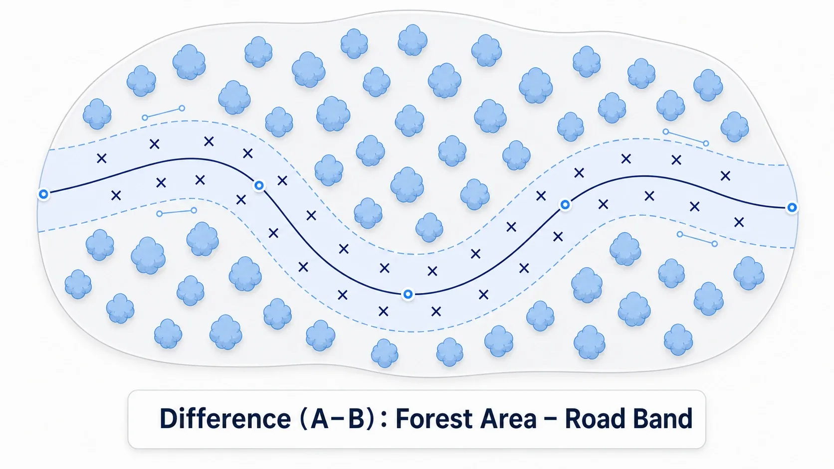
What you use is Difference . This is the node that "subtracts range B from range A".
- A: the range to scatter forest (the whole hill)
- B: around the path drawn with the spline (a band range)
- A − B: scatter trees only in the range excluding the path band
Do this and no trees grow on and around the path drawn with the spline, and a clean path runs through. And re-bend the spline, and the tree-free band follows that shape too . You're freed from the manual work of deleting trees each time you re-run a path.
Hands-On: Growing the Forest-and-Path Graph
An open-field RPG's road, a survival exploration map, a walking sim's forest. "A forest on a hill with a path running through it" is a staple scene of an outdoor map. Here we build one, reusing the hill made with Landscape, growing a graph in three stages.
We're building a forest that scatters trees over the whole hill, excludes cliffs with a slope filter, and removes trees in a band along the spline path .
Here's what it looks like running. A forest spreads over the hill, no trees on the cliffs, and a tree-free band runs along the path. And re-bend the spline, and the band along the path instantly follows and changes shape . The work of deleting trees that hand-scattered Foliage would need, PCG finishes just by moving the line.
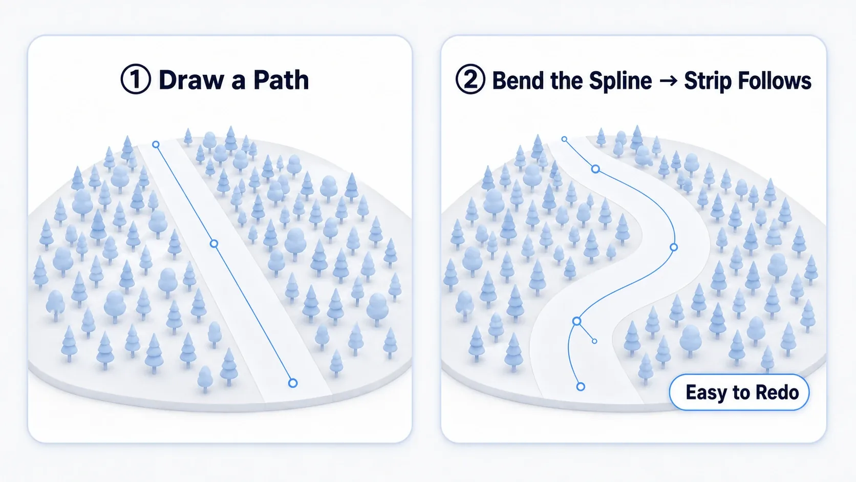
The Graph's Three Stages
Add three nodes in order to grow the graph.
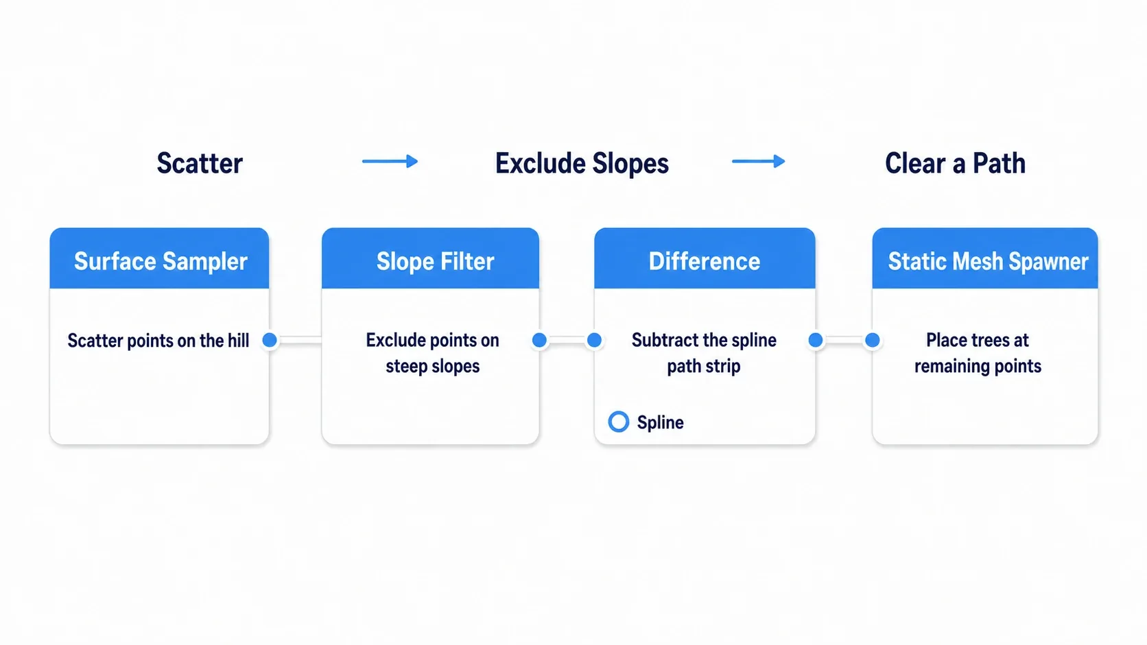
PCG graph (forest and path)
1. Surface Sampler (scatter points on the hill's surface)
  → 2. slope filter (exclude points on steep slopes)
  → 3. Difference (subtract the spline path's band)
  → Static Mesh Spawner (place trees on the remaining points)
| Stage | Node | Role |
|---|---|---|
| 1. Scatter | Surface Sampler | Scatter points over the whole hill |
| 2. Exclude cliffs | slope filter | Discard points on steep slopes |
| 3. Cut the path | Difference (spline) | Subtract the path band to remove trees |
Verifying It
Regenerate the PCG and you get a forest spread over the hill, no trees on the cliffs, and a tree-free band along the path . Then try bending the path's spline. If the band follows the shape, it worked.
Here's how to narrow it down when it doesn't work.
- No trees come out at all → whether the Surface Sampler's target points to the Landscape . Check that the PCG Volume overlaps the Landscape
- Trees grow on cliffs too → the slope filter's threshold. Lower the threshold to exclude even gentler slopes
- Trees remain on the path / the band is off → check the band width of the spline passed to Difference, or the spline reference
Two things to take away.
- Redoing is free: this is the decisive difference from Foliage. Density, cliff exclusion, path shape, change the graph and everything re-scatters. No work of deleting by hand
- Add conditions to get smarter: the more you stack conditions like slope filter and Difference, the more natural the placement. Scatter first, then exclude, growing the graph in stages. If the load of mass placement worries you, lighten it with combinations of Nanite meshes or LOD and culling
Bonus: Good to Know for Later
Add variation to size and rotation. If all trees are the same size and same orientation, it looks obviously "copied". Randomly varying the size and rotation of each scattered point with Transform Points-type nodes makes a natural forest. Along with density (point count, Density), this "variation" is the deciding factor for realism.
Regeneration is basically baked in the editor. The PCG in this article generates (bakes) placement in the editor for use. There's also a use of generating in real time during gameplay, but the load and design get much harder at once, so keeping to the use of baking and fixing in the editor first is the recommendation.
Mass placement is light thanks to instancing. The trees Static Mesh Spawner places are instanced internally (drawing the same mesh together), so even thousands run relatively lightly. Still, overdo it and it gets heavy, so decide the density while measuring with stat unit and the like. What "drawing them together" actually means is covered in Cutting Draw Calls with Instanced Static Meshes.
Summary
PCG, scattering by rules, is grown with this flow.
| Stage | What to do | Node |
|---|---|---|
| Scatter | Scatter points on a surface | Surface Sampler |
| Place | Place meshes on points | Static Mesh Spawner |
| Narrow | Exclude cliffs | slope filter |
| Cut | Remove the path | Difference (spline) |
And the principle running through it is to hold rules, not results . Because changing the rules auto-updates the results, you can make the decoration of a wide map work even solo.
With this, you can build the look of an open field without relying on manual work. In your map, where does the path the player most wants to walk run through? First, scatter trees on a hill and run a single path through them.
Further Learning
- Making Terrain with Landscape — as a continuation of the hill and Foliage
- Optimizing High-Poly Meshes with Nanite — the foundation supporting mass placement
- Performance Optimization (LOD, Culling) — measuring when you overdo it